|
June
25th. It has
been a while since I posted any progress, although there has
been quite a lot.
However,
today I did some work in my machine shop and produced some
experimental parts (for other projects) as well as the Stub
axles for the front and rear wheels on the car. I am very
happy with the result.
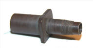
I started
with some 1/2" diameter brass bar and machined the stub axles as
per my drawing, which also enable them to fit the lotus 72D kit
as part of the trans-kit.
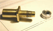
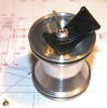
 Looks a little rough, but
that is more the digital picture. The aluminum part is the
wheel nut without the hex machined on it.
Looks a little rough, but
that is more the digital picture. The aluminum part is the
wheel nut without the hex machined on it.
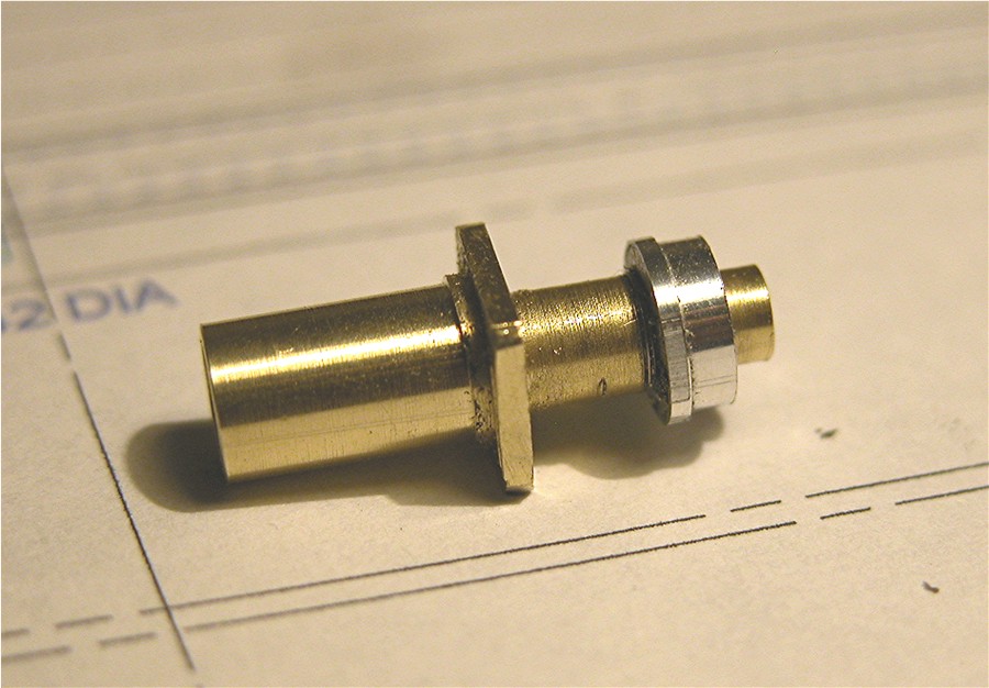
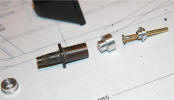
Very fine
thread
 4mm x 0.35 pitch. The part is a bit dirty as you can see.
The length of the part is approximately 0.75".
4mm x 0.35 pitch. The part is a bit dirty as you can see.
The length of the part is approximately 0.75".
 Just
so you see the nut does actually fit perfectly, the way I wanted
it to. When the wheel hub is in place, it should be
clamped by the nut and have a half thread showing out the end of
the nut. We shall see! :) Just
so you see the nut does actually fit perfectly, the way I wanted
it to. When the wheel hub is in place, it should be
clamped by the nut and have a half thread showing out the end of
the nut. We shall see! :)
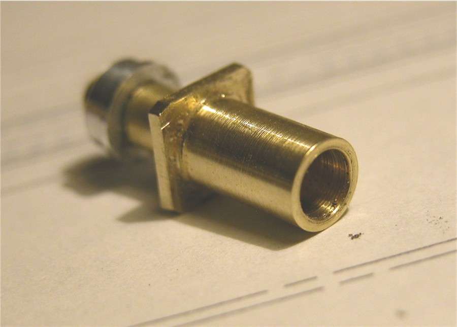
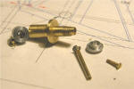
The back
side has a shoulder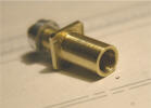 to give enough space for the pins and nuts that locate the
wheel. It is hard to see in this picture. The rest
of it is the correct diameter to fit the suspension hubs, front
and rear, supplied in the Tamiya kit. I'm thinking of
putting nylon bushes in the hubs on my kit.
to give enough space for the pins and nuts that locate the
wheel. It is hard to see in this picture. The rest
of it is the correct diameter to fit the suspension hubs, front
and rear, supplied in the Tamiya kit. I'm thinking of
putting nylon bushes in the hubs on my kit.
To keep
everything spinning, the inner part will be a push fit, no glue
needed. Tight tolerance on such small items.
I don't
think I will supply the parts like this, as you will want to do
some work. These axles are not supposed to be brass.
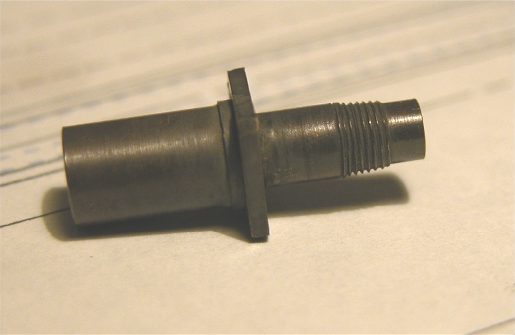
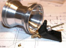
Well low and behold with a little magic, look what can be done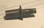 almost looks like it should. Now you can really see the
shoulder on the back side.
almost looks like it should. Now you can really see the
shoulder on the back side.
 Damn! that stuffs good!
That is a
few seconds submerged in some "Blacken-it", then removed and let
dry, then washed in hot soapy water. Because of the
effect, I think I'm going to make more parts in brass for the
kit, that should be metal. (Umm! Methinks I need
to stock some of this?!?)
That's
all for this day, although the front sub-frame has been redone,
the rear wing end plates are completed and an aluminum prototype
of the tub and drivers seat was done, but I found some mistakes
and an easier way to produce it.
Do you
want to put the tub together with rivets, or would you prefer it
to just look like rivets? That's kind of rhetorical, more
like Henry Ford saying "You can have any color you like as long
as it's Black" :) So guess what it's going to be. :)
June
26th.
Back in the "model factory", my machine shop, I have fabricated
the Universal joint hubs that will go inside the wheels and at
the disc brakes. They looked huge on the drawings, but in
my stubby little fingers, the parts are almost lost! (1/4"
OD.) I have a little more to do on them, hence no picture today.
But due to the complex fabrication of these parts, I have
decided to cast them in white metal. The result will be,
half shafts that actually drive the parts they are supposed to
when the axle is turned. In other words; at the front you
spin the wheel and the disc brake will spin, even when you move
the suspension. At the rear, no matter which wheel you
turn the disc brakes will turn and at the same time the wheel
and disc brake on the other side will turn.................that
is as long as YOU assemble it correctly. :)
So far
the only parts that are going to be white metal....the brake and
clutch cylinders on the front, the hub universal joint housings,
pinion housing for the rack an pinion steering, upper and lower
suspension "wishbones" and parts of the engine, Oh! and the
wheel centers. It is the best way to get the cast look on
them.
|
|
July 3rd.
I have been having fun in my machine shop again, and after
fabricating the first stub axle, I have decided on a different
method of assembly to make it easier. Instead of
push/transition fit, the universal joint will be a slide fit
with a screw to hold it in place.
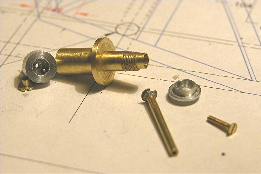
So here is the new stub axle
and assembly.
 I have not shaped the mounting boss to a square as you can see,
but it will be on the finished item. If you look carefully
inside the UJ housing you can see a round "key", which is what
will supply drive through the half-shaft.
I have not shaped the mounting boss to a square as you can see,
but it will be on the finished item. If you look carefully
inside the UJ housing you can see a round "key", which is what
will supply drive through the half-shaft.
The small brass piece next
to the UJ housing is the parts that will be inserted in each end
of the half-shafts and you can see the notch in it, which will
engage the key inside the housing. That is a prototype
half-shaft in the picture I have used just to show some
indication of what it will look like. The other aluminum
part is the cap to the Universal joint. You will notice
the "bellmouth" opening on it to allow more motion from the
half-shaft. The screw is a 1/4" long flat-head 00-90,
which is inserted in the end of the stub axle and screws into
the back of the UJ housing.
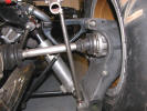
 Here all the parts have been
assembled inside the rear suspension support from the Tamiya 72D
kit. You can see how the half-shaft has movement when
assembled. And yes that is a re-machined wheel that you
have not seen.
Here all the parts have been
assembled inside the rear suspension support from the Tamiya 72D
kit. You can see how the half-shaft has movement when
assembled. And yes that is a re-machined wheel that you
have not seen.
Today I also worked on the
wheel center, which currently is a blank, with the profile of
the rear of it machined in, including the axle hole.
 And there you have
it...........the assembly mounted in the wheel, to test
clearance and position. All seems well! :)
And there you have
it...........the assembly mounted in the wheel, to test
clearance and position. All seems well! :)
Nov. 25th 2007:
As most of you know, it's been a while since there was anything
new posted here. That was because a great deal of the work I had
done was wrong. Although I had drawings from Lotus, they had
gone through an evolution just as the car, so I was building a
72E and not a 72C. :(
That was a little
disheartening after all the work I had put in, however, most of
the information has been straightened out with the aide of a
gentleman called Erich Walitsch in Austria. Thank you Erich!
However, the basics are the
same, so I have left most of the text and pictures of this
project pretty much the same.
Also the website business
really increased and took all my spare time I had to work on the
project. I am re-dedicated now, so you should see more on the
progress soon.
There is a change on the
front sub-frame, a minor change to the axles, also a slight
change on the drive shafts, but as these were all test pieces
it's not so bad.
I have also found a machine
shop locally that can compete with the quality and price of
Japan, which is great! Especially if something needs changing. I
can just drive there and explain it. :)
I have just about finished
the body sides and the "buck" to enable the windshield to be
vacuum formed.
Next weekend I will try to
post some pictures of the new "correct" progress.
If you
want to see just the pictures click
here.
March 16th. 2008.
I have made some great progress with the tub, bodywork and
started on the engine.
The floor will be aluminum
and the tub is going to be made out of very thin photo etched
sheet aluminum and you will have to fold it into shape.
Some of you may not like this, but I am going to supply every
kit with miniature rivets for the tub. You will be able to
assemble the parts without them, but you will want to install
them. The holes will be there for them.
I have completed all the
work on the left side bodywork and side pod. I have to give them
a final coat and sand them both down for smooth finish, to
reproduce the best item when it comes to molding them. I will
post some pictures after I have that done. The side pods have
the proper aero shape inside them as well. I am really happy
with them.
The engine is still in
process, it is taking a while because of the amount of parts.
You will get the resin block, cylinder heads, inlet manifold and
Cam heads as separate pieces, with white metal cam covers. There
will also be end plates. The whole thing should go together
pretty much like the regular engine. There are a lot of pieces
to make for it. As soon as I have the engine done I will be able
to work on the Air intake box.
The nose is almost completed
as well, just some more minor adjustments and it will be ready,
probably 2 more weeks before I actually get to finish that
though.
To be
continued.........................Page
3 |