![]()
![]()
![]()
![]()
![]()
![]()
![]()
![]()
![]()
![]()
![]()
![]()
![]()
![]()
![]()
![]()
![]()
![]()
![]()
![]()
![]()
![]()
![]()
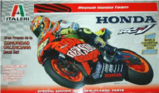
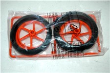
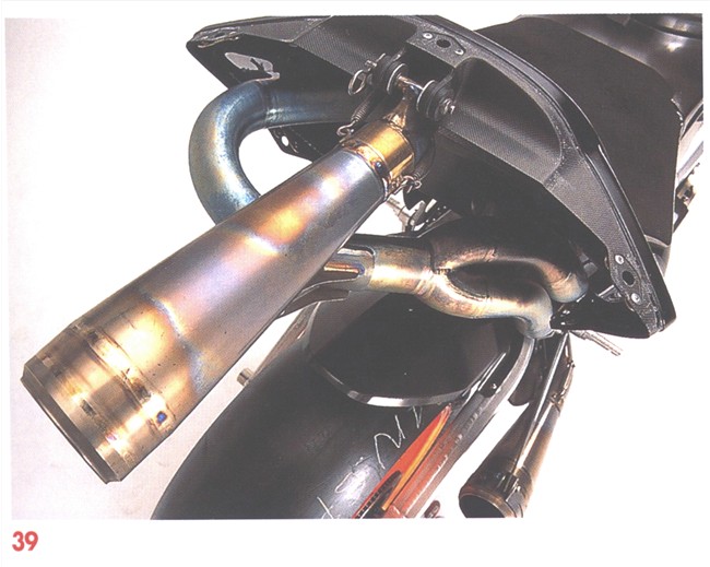
Honda RC211V, 2003, Valencia
This is the kit produced by Italeri. It is 1:6 scale, so BIG scale
As with a lot of larger scale kits of models that have been produced in smaller scales, there are not many parts, in fact there are less than in the Tamiya 1:12 scale kit.. This really disappoints me, but in another way really pleases me. It is because of "what pleased me" when I opened the box, I decided to write this as I build it. It just "BEGS" for detail!!!

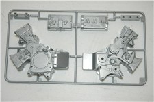
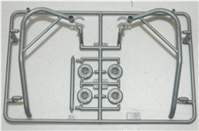
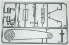
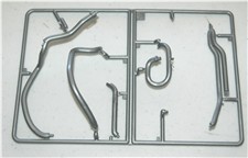
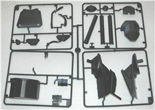
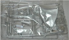
 I'm sure you have noticed that some parts are
missing from the sprue's. That is because I started on it before I decided to
do a W.I.P. of it. Most obvious are the Fairing (which I had already been
working on) and front fork outer legs, (which I threw away).
I'm sure you have noticed that some parts are
missing from the sprue's. That is because I started on it before I decided to
do a W.I.P. of it. Most obvious are the Fairing (which I had already been
working on) and front fork outer legs, (which I threw away).
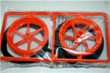
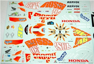
I decided that not much of the kit was any good, maybe the wheels tires and decals would be the only parts I use. I still have not made a final decision on that yet. The kit is so wrong, and off scale any parts that I do use will have major modifications. It seems so easy, to me, for a company to make a kit to "Scale" when it is so big. I find it hard to believe it is a bad as it is.
I started with the front end,
the forks; after checking the ones in the kit for scale size, it was time to
discard all the fork parts and start from scratch..
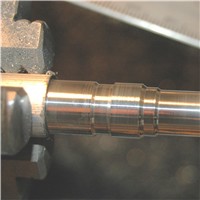
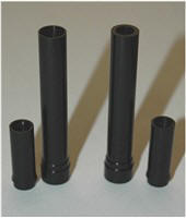
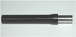
So after working out the dimensions and making drawings, I started machining
the outer legs from Aluminum bar stock and had them anodized.
 (As I was
getting some wheels anodized I added the fork legs to the quantity, otherwise
it would not be economical to do this, as most companies have a minimum charge
of $80.00.)
(As I was
getting some wheels anodized I added the fork legs to the quantity, otherwise
it would not be economical to do this, as most companies have a minimum charge
of $80.00.)
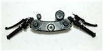
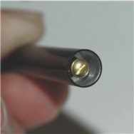
I decided to machine them with the bottom of the leg nearest the chuck, that
way I could keep everything concentric, as the forks will be operational. They
are going to be many parts to each leg. The outer leg itself will be two
anodized parts, with a threaded aluminum cap on each leg plus adjusting screws
in each cap.
Here you can see what I mean.
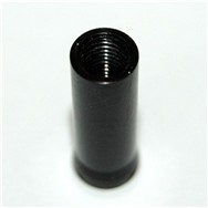
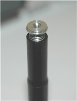
I have to machine a square on top of the cap as per the real bike.
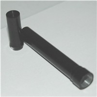
After the legs came back from being anodized I machined the inside of the
lower leg for the inner sliding leg.
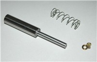
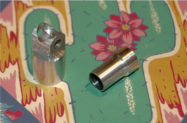
I machined the slider from
Aluminum, with the idea of using stainless steel tube for the actual leg so it
would not scratch. I purchased a 1ft length of 5/16" OD stainless tube and
polished the outside. The aluminum part is machined to slide inside the tube
and then have a reduced section extending out with a threaded hole to accept a
2-56 screw on the top, and then be glued in position. Doing this allows me to
make the bottom of the leg separate and also slide it into the bottom of the
stainless tube
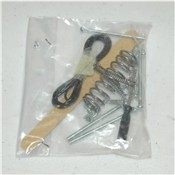
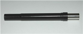
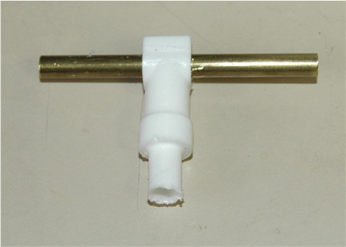
Here is the inner leg with spring and retaining screw & washer.
 Slipping the slider into the fork leg with the spring in place
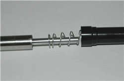 and fully depressing the spring allows me to screw in the retaining screw
 this stops the slider from dropping out and sets the length of the extended
fork leg. Here you see it assembled
this stops the slider from dropping out and sets the length of the extended
fork leg. Here you see it assembled
 without the top, and with it.
 .
.
Then I started on the bottom
of the leg. I could not find the correct square stock size I needed so I took
some round bar, drilled a hole in it 0.180" deep, then milled a square.
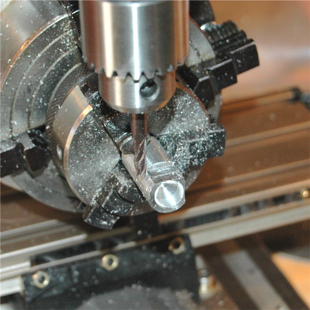 (Not quite sure why I'm doing this in aluminum though. ;) After completing the
milling I made a radius on the end and drilled a hole in the side for the
axle.
(Not quite sure why I'm doing this in aluminum though. ;) After completing the
milling I made a radius on the end and drilled a hole in the side for the
axle.
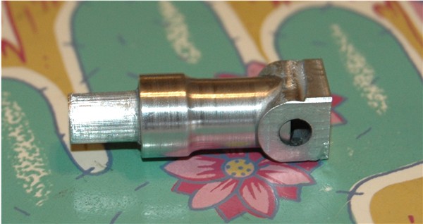
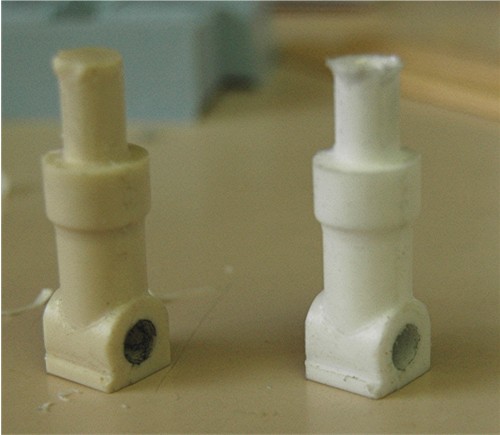
 Using a piece of a screwed up fork leg. (That's why drawings are important)
Glued it in the top, along with a piece to fit inside the stainless slider,
then finished shaping it so I can cast it in resin. Here is the part before I
cast it
Using a piece of a screwed up fork leg. (That's why drawings are important)
Glued it in the top, along with a piece to fit inside the stainless slider,
then finished shaping it so I can cast it in resin. Here is the part before I
cast it
 It looks a lot better now.
To create the mold, I inserted
two pieces of rod, 1 in each side of the axle hole (rather than drill it out
and use one piece) the nice part about casting. :) Here is the mold I made
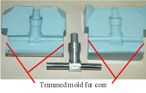 and you can see where I trimmed it.
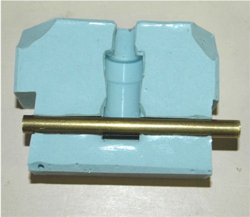
Now it's my time in the
kitchen, I "bake" the mold in the oven for 5 minutes at 150F, remove it then
pour the resin. Here it is with the "dummy axle" core
 and the finished
 casting 30 minutes later. I forgot to use a releasing agent on the core, so I
had to chuck the part in the freezer for a few minutes and push it out on the
drill press.
casting 30 minutes later. I forgot to use a releasing agent on the core, so I
had to chuck the part in the freezer for a few minutes and push it out on the
drill press.
 That's it for now on the fork legs. I have to produce the drawings so that I
get the Brake caliper mounts in the correct place. So I'm going back to the
fairing for now.
That's it for now on the fork legs. I have to produce the drawings so that I
get the Brake caliper mounts in the correct place. So I'm going back to the
fairing for now.
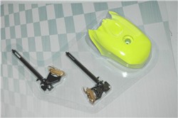
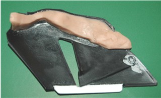
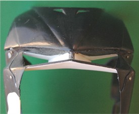
The fairing came in four
pieces, but not the correct four pieces. The bottom section was split in two
pieces and the top was split down the middle.
First off I glued all the parts together so I could reshape it and have it
look right. Then I cut it apart at the seems where it is supposed to be
separated. I used my model knife with a new blade, almost lost a couple of
finger tips and definitely drew blood in this process.
At least this way I will finish up with the top of the fairing, two side
panels and the bottom section.
You can see from this picture that the fairing is missing so much detail, but
that will soon change. :)
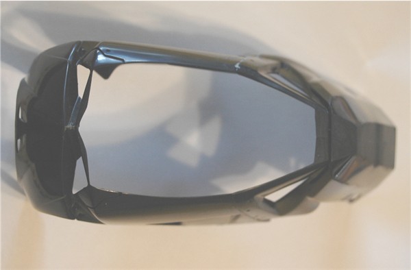
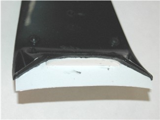
The nose section sanded at the
kit seem before cutting it apart
 These are the seem lines I want to cut through
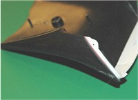
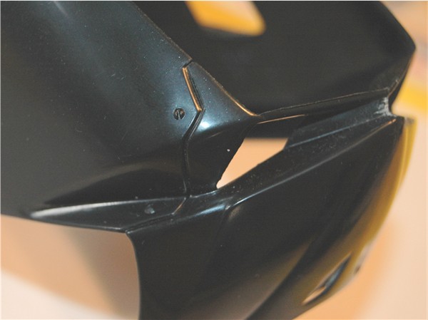 As you can see this was not an easy undertaking with all the different
directions the seems go. Hence the blood loss.
As you can see this was not an easy undertaking with all the different
directions the seems go. Hence the blood loss.
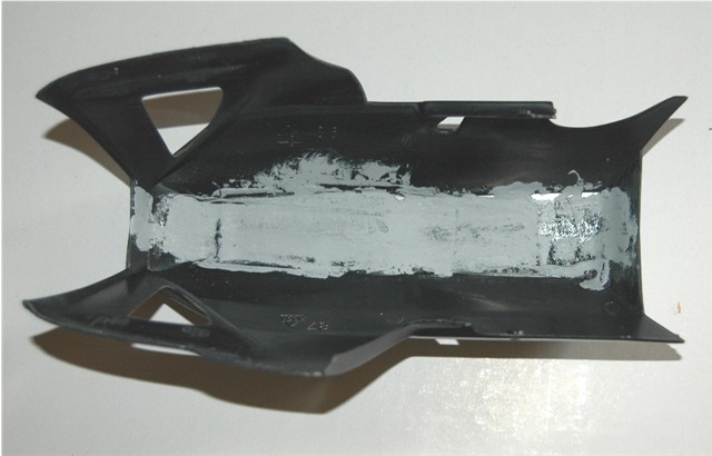
I took the bottom section and smoothed the outside seem
 and loaded the inside with putty
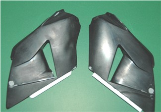
 I'll leave that for a week or so before working on the inside of it. I cleaned
up the side panels and I was going to re-cast them, but decided as I'm only
making the one bike, that I did not need to bother. Later, that turns out to
be a bad decision! Added strips
I'll leave that for a week or so before working on the inside of it. I cleaned
up the side panels and I was going to re-cast them, but decided as I'm only
making the one bike, that I did not need to bother. Later, that turns out to
be a bad decision! Added strips
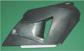 for the screws to attach the pieces together when finished.
I started the reworking of the
fairing to include the "ram air" ductwork which is non existent. I used
"Sculpey" to shape the duct on the inside of the fairing. I got it to a shape
 I was happy with, (a little oversize so I can finish shape it after it's
cured) I realized I should have used some cling film under it, because it
needs to be "baked" to cure, and that would have allowed me to remove it
easily. Now if I try to remove it, it will change shape. Oh well! I'll just
put it under a halogen lamp (thinking "I should have made a copy of these,
no! it will be fine. I'll just keep an eye on it") Yup! you guessed
it.........................................melted the fairing. Cured the
sculpey though. ;)
I was happy with, (a little oversize so I can finish shape it after it's
cured) I realized I should have used some cling film under it, because it
needs to be "baked" to cure, and that would have allowed me to remove it
easily. Now if I try to remove it, it will change shape. Oh well! I'll just
put it under a halogen lamp (thinking "I should have made a copy of these,
no! it will be fine. I'll just keep an eye on it") Yup! you guessed
it.........................................melted the fairing. Cured the
sculpey though. ;)
It's not too bad
 although the picture does not really show how bad. Time to get out the
Milliput. After a little while I managed to get the outside of the fairing
back to shape. You can see the extent of the warping in this picture
although the picture does not really show how bad. Time to get out the
Milliput. After a little while I managed to get the outside of the fairing
back to shape. You can see the extent of the warping in this picture
 Looks a little like "Atom Heart Mother" (Pink Floyd, for those wondering.) I
turned to the inside and worked the "Dremel" over it for a while and got it
fairly reasonable for now
Looks a little like "Atom Heart Mother" (Pink Floyd, for those wondering.) I
turned to the inside and worked the "Dremel" over it for a while and got it
fairly reasonable for now
 That's the nice part about Milliput, it can be made very thin once cured, so
it is great for repairs.
That's the nice part about Milliput, it can be made very thin once cured, so
it is great for repairs.
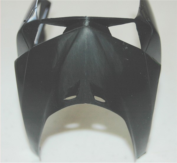
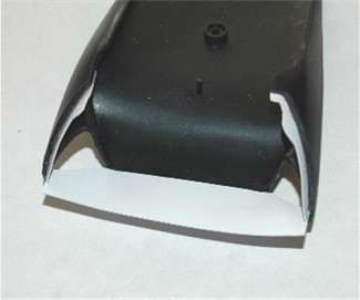
I reworked the nose section
with the ram air ducts in it and reassembled all the fairing parts to check
for fit using 000-120 x 1/8" long "binding head" screws. I will probably use
the next size up (00-90) for the finished item.
With it all assembled I can see where I need to
add/trim material and do a little more reshaping, especially at the seems
 Having the fairing assembled again will help with the modifications needed on
the frame and aide in the fabrication of the non existent, air-box & fuel
tank, new tank cover and seat support.
Having the fairing assembled again will help with the modifications needed on
the frame and aide in the fabrication of the non existent, air-box & fuel
tank, new tank cover and seat support.
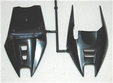
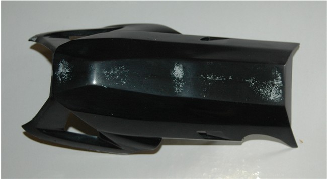
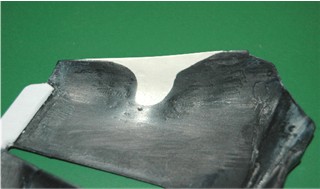
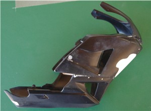
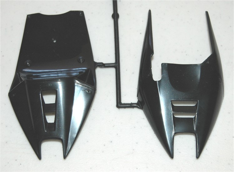
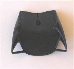
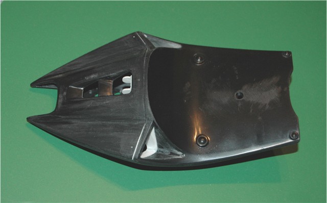
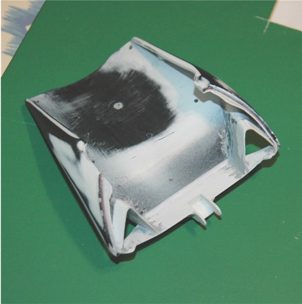
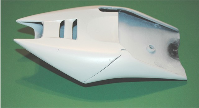
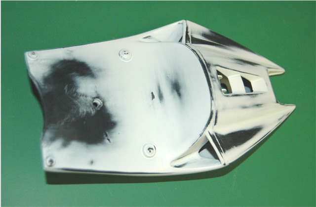
I tend to hop about a little
on this project. Now I have moved on to the Seat section, which will receive
similar treatment as the fairing. Remember this is how it comes in the kit
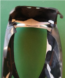
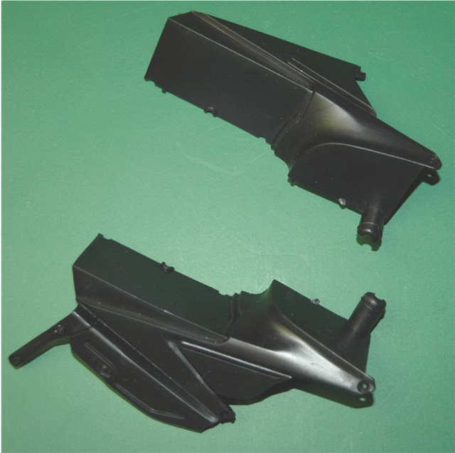
 I need to make it a two piece section, but initially that will require me to
make it into five pieces., then into three pieces,, then ultimately two
pieces.
I need to make it a two piece section, but initially that will require me to
make it into five pieces., then into three pieces,, then ultimately two
pieces.
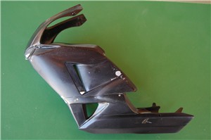
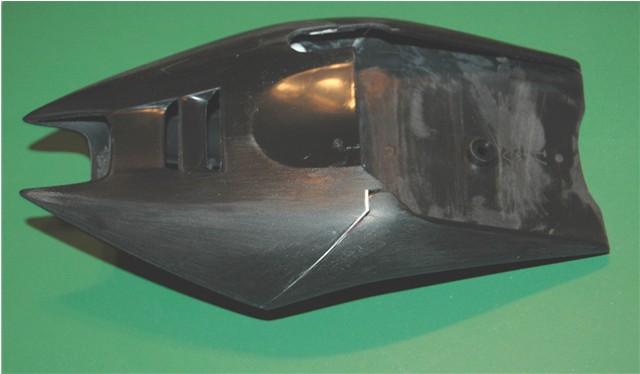
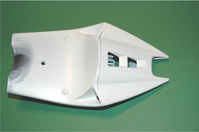
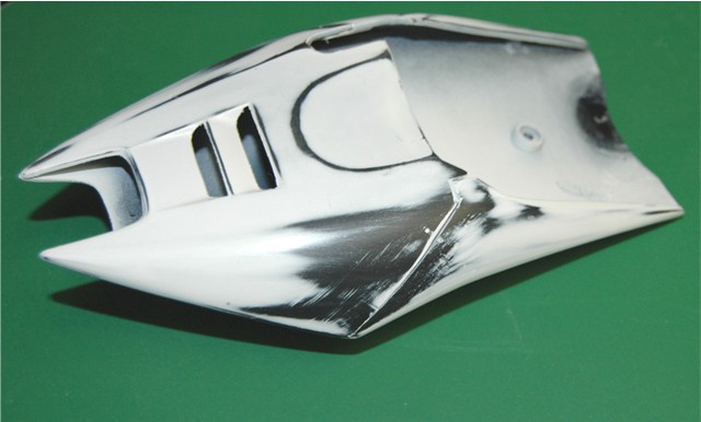
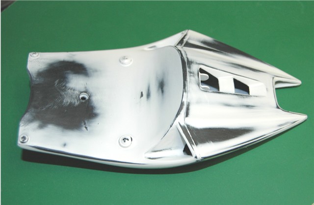
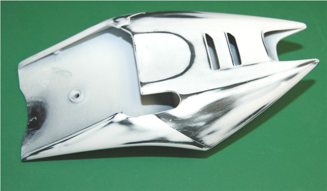
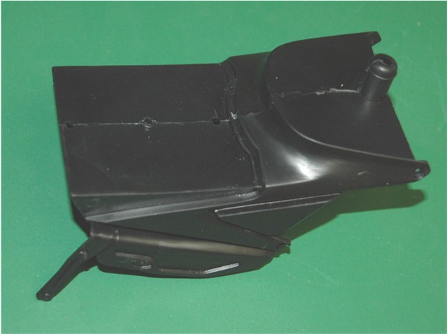
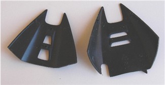 There is a lot of work to do to this as this is the result I want to achieve
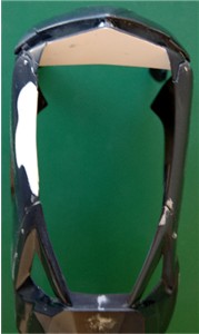
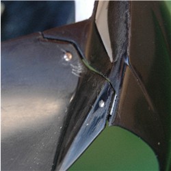
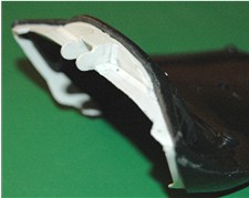
 So here we go. Using thin plastic strip, rod and sheet I made the pieces for
the Dzus fasteners to attach to and the basis for the exhaust bracket.
So here we go. Using thin plastic strip, rod and sheet I made the pieces for
the Dzus fasteners to attach to and the basis for the exhaust bracket.
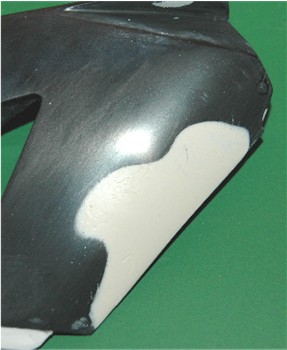
I am really happy with it at the moment, but there is still more to do on the
vents in the seat and making sure everything fits together perfectly.
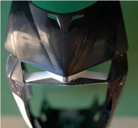
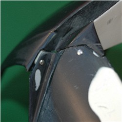
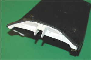
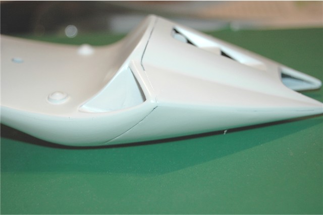
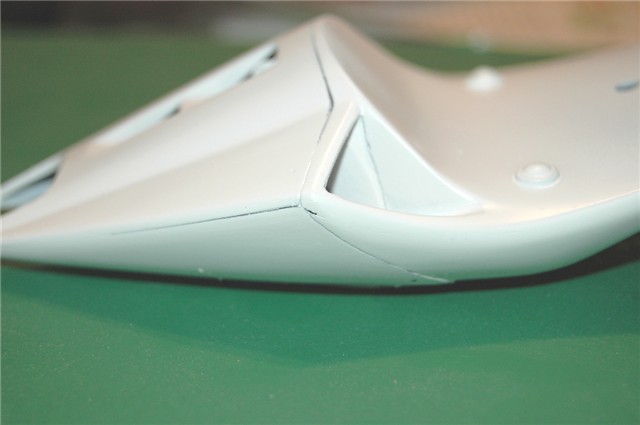
 Material was added where needed to make it fit just right. Here you see the
added material for the seat vents
Material was added where needed to make it fit just right. Here you see the
added material for the seat vents
 Now it's time to do some more final fitting, filling and sanding to be ready
for paint.
Now it's time to do some more final fitting, filling and sanding to be ready
for paint.
I put it all
together with tiny dabs of Super Glue so I could work it in one piece,
thinking it would be easy to take apart when done. Once it was together I
sanded and shaped so there would be no uneven joints.
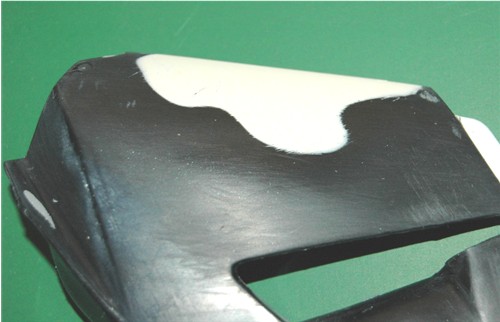
Then sprayed it with Tamiya's white fine primer
 you can see where the super glue was used by the solid look at the joints
 this also showed me where I would still need to fill and add more material,
that is the reason for using the white primer, then proceeded to sand and
spray again, and sand again. I went through this process 3 times, changing the
grit each time.
this also showed me where I would still need to fill and add more material,
that is the reason for using the white primer, then proceeded to sand and
spray again, and sand again. I went through this process 3 times, changing the
grit each time.
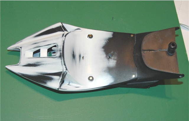
 I plan on having the seat fit on the support via 4 screws where you see the
four molded in screws are, and eliminating the center screw the kit wants me
to use, but first I have to modify the seat support as it will not allow me to
do this in it's original form.
I plan on having the seat fit on the support via 4 screws where you see the
four molded in screws are, and eliminating the center screw the kit wants me
to use, but first I have to modify the seat support as it will not allow me to
do this in it's original form.
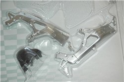
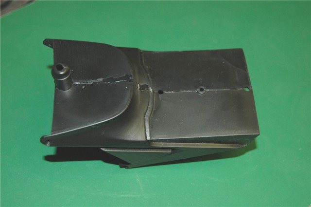
To start with I assemble the kit parts for the
support and remove the exhaust bracket and heat shield from the bottom.
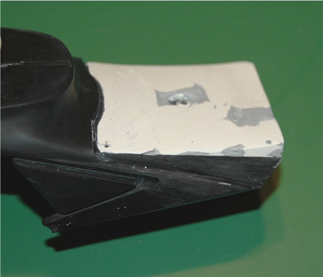
 Now it's time to get the Milliput out again to build up the seat support to
enable me to use the screws. I build up the base with a thin layer of Milliput,
and to ensure I get the correct shape, I use "cling film", which I wrap over
the top of the support then position the seat on top and squeeze into place. I
have to do this a few times to trim the excess Milliput until the seat sits
firmly on the matching edge of the seat support.
Now it's time to get the Milliput out again to build up the seat support to
enable me to use the screws. I build up the base with a thin layer of Milliput,
and to ensure I get the correct shape, I use "cling film", which I wrap over
the top of the support then position the seat on top and squeeze into place. I
have to do this a few times to trim the excess Milliput until the seat sits
firmly on the matching edge of the seat support.
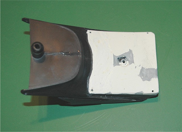
 I fill in the small defects with Tamiya putty then will sand it all into a
nice smooth finish. For now I am going to fit the seat correctly then drill &
tap the holes for the 0-80 screws that will eventually hold the seat in place.
I fill in the small defects with Tamiya putty then will sand it all into a
nice smooth finish. For now I am going to fit the seat correctly then drill &
tap the holes for the 0-80 screws that will eventually hold the seat in place.
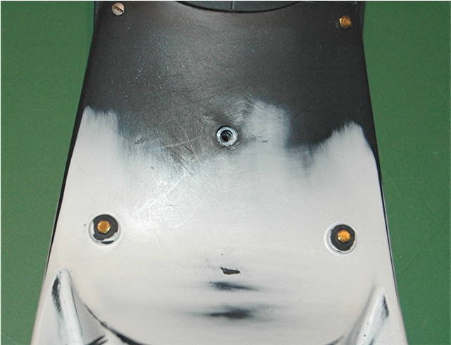 Here you can see I have removed the molded in screw heads and have the seat
attached temporarily with brass 0-80 hex screws (and one slotted flat head, I
ran out of hex screws) I will eventually fill the hole in the middle of the
seat, although that is not completely necessary as the seat pad will cover it.
It's just that I will know it's there and it would be seen when the seat is
removed.
Here you can see I have removed the molded in screw heads and have the seat
attached temporarily with brass 0-80 hex screws (and one slotted flat head, I
ran out of hex screws) I will eventually fill the hole in the middle of the
seat, although that is not completely necessary as the seat pad will cover it.
It's just that I will know it's there and it would be seen when the seat is
removed.
I have been trying to decide the order in which I will paint the seat, because the tail section requires two completely different colors and methods to achieve it. I think I will spray the insides with semi gloss Black first, then with the top lay down the white primer, followed by the yellow and clear coat and attach the Dzus fastener plates while the clear is still tacky.. The bottom with be painted gloss black and then the metallic color and clear coat the same way. But these are just thoughts right now. I'll cross that bridge when I come to it.
In the meantime I will make a new resin tank cover, and start work on the fuel tank and air-box.
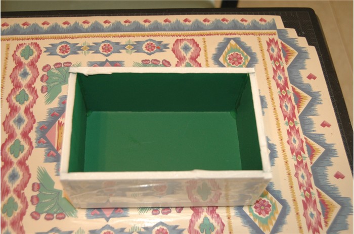
I made a mold of the metal tank cover from the
kit, which has a pretty good outer shape so will work fine. This will be a one
piece mold. First I make the mold box from foam poster board.
 Then prepare the tank cover adding some sculpey to the inside at the front.
The reason for this is to stop the rubber from flowing into the inside when
making the mold.
Then prepare the tank cover adding some sculpey to the inside at the front.
The reason for this is to stop the rubber from flowing into the inside when
making the mold.
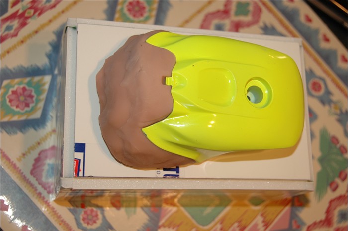
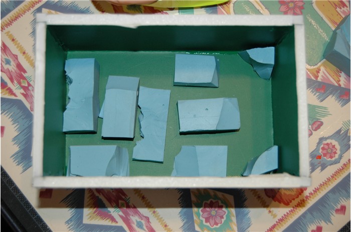
 Then prep the box with used molds cut up and placed in the bottom to raise the
cover off the base to allow the mold rubber to flow around it.
Then prep the box with used molds cut up and placed in the bottom to raise the
cover off the base to allow the mold rubber to flow around it.
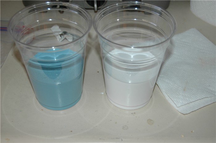
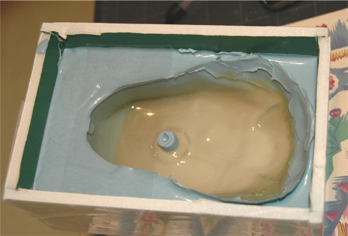
 I use Micro Mark's RTV rubber molding material. It is easy to use. Just
measure out even two cups of each solution then mix together. It sets at room
temperature. Before pouring it into the box I generally bang it on the counter
top a few times to make the trapped air escape.
I use Micro Mark's RTV rubber molding material. It is easy to use. Just
measure out even two cups of each solution then mix together. It sets at room
temperature. Before pouring it into the box I generally bang it on the counter
top a few times to make the trapped air escape.
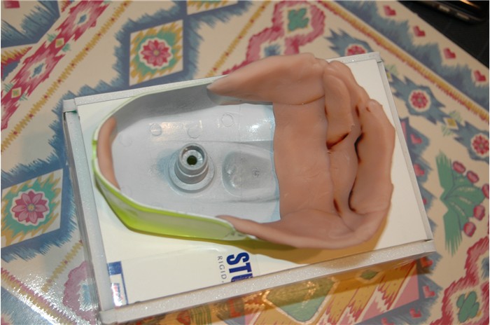
 Here is the tank cover in the rubber mold solution
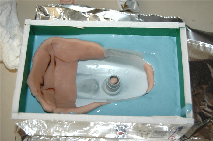 I also used some scotch tape to prevent the rubber coming in at the back end.
You will also see a small plug in the tube in the middle, to prevent the
rubber coming up through it. Now I have to leave it for 4 hours to allow it to
set.
I also used some scotch tape to prevent the rubber coming in at the back end.
You will also see a small plug in the tube in the middle, to prevent the
rubber coming up through it. Now I have to leave it for 4 hours to allow it to
set.
(This is where I take time to answer emails and pack items to ship)
Four hours and a bit, later
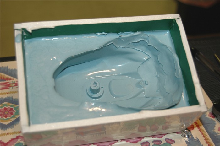
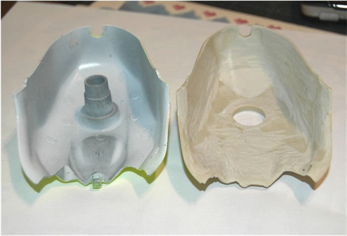
 I'm happy with the result. Now it's time to mold the new tank cover. I want it
hollow obviously and the easy way to do this is pour the resin mix in the mold
then "swish" it around in the mold until it sets. Doing this I prefer to use
"Alumilite" resin mix as it sets up in approximately 90 seconds, a little
longer on thin parts. It will take 3 or 4 mixes to get the tank cover
completed, here is the first wash.
I'm happy with the result. Now it's time to mold the new tank cover. I want it
hollow obviously and the easy way to do this is pour the resin mix in the mold
then "swish" it around in the mold until it sets. Doing this I prefer to use
"Alumilite" resin mix as it sets up in approximately 90 seconds, a little
longer on thin parts. It will take 3 or 4 mixes to get the tank cover
completed, here is the first wash.
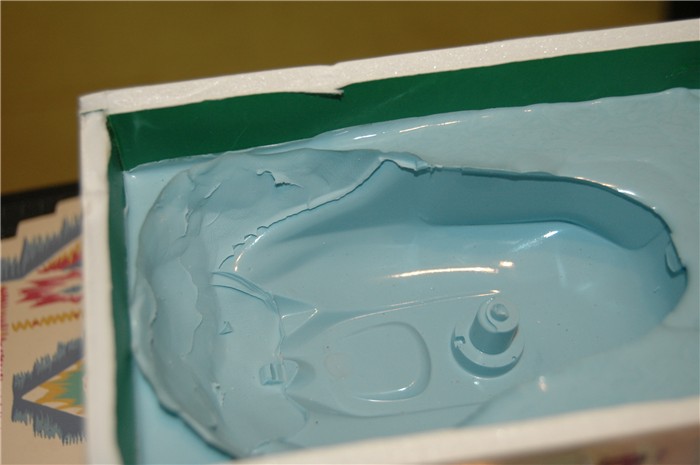
 You can see the very thin shiny coating at the back of it. Obviously the
thickness is inconsistent, but I will take care of that in another stage. Here
it is after the last wash.
You can see the very thin shiny coating at the back of it. Obviously the
thickness is inconsistent, but I will take care of that in another stage. Here
it is after the last wash.
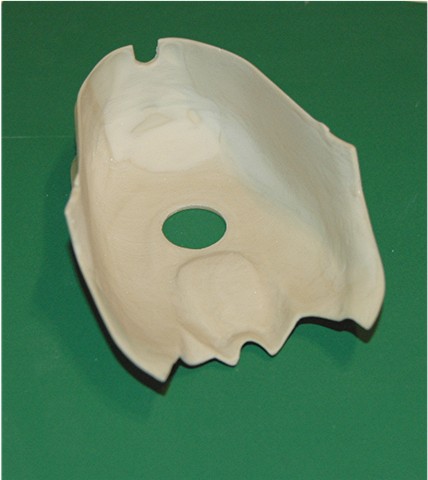
 Although the resin sets up quickly, it does not get really solid for a little
while when its so thin, so I have to leave it for a while again. This is what
I finished up with after carefully removing it from the mold.
Although the resin sets up quickly, it does not get really solid for a little
while when its so thin, so I have to leave it for a while again. This is what
I finished up with after carefully removing it from the mold.
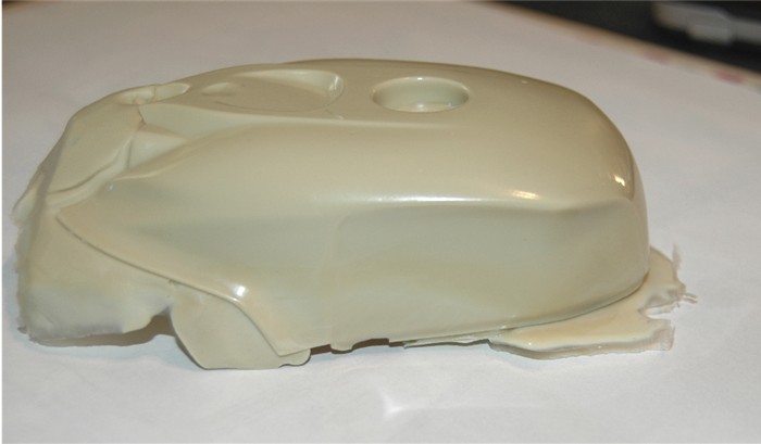
 There was obviously an air bubble in the mold that I did not notice and while
the resin heated during curing, expanded the air in the pocket and produced a
dent in the top of the tank cover, but that is not a big deal. Overall its
good, just need a little work removing the flash and with a Dremel to thin it
down. The initial clean up
There was obviously an air bubble in the mold that I did not notice and while
the resin heated during curing, expanded the air in the pocket and produced a
dent in the top of the tank cover, but that is not a big deal. Overall its
good, just need a little work removing the flash and with a Dremel to thin it
down. The initial clean up
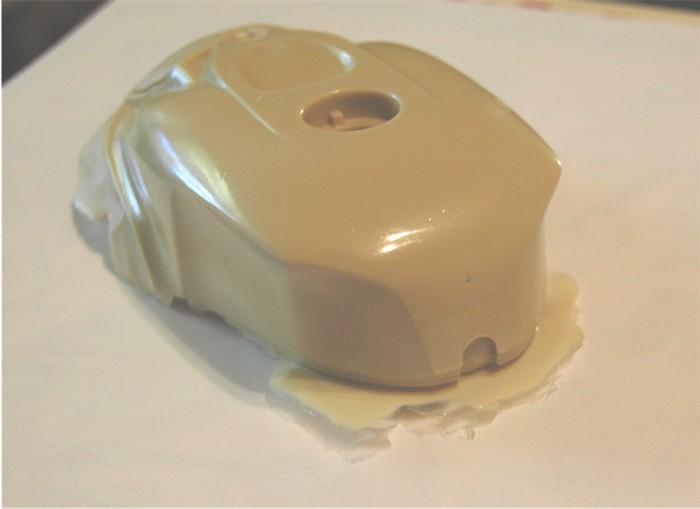
 just rough. It will take a few more visits to my Hi-Tech grinding booth and
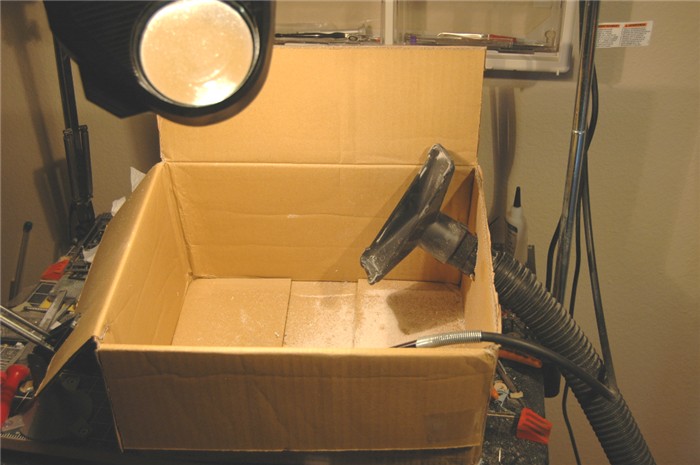 the Dremel to get it where I want. It is a little time consuming but what I
finished up with
the Dremel to get it where I want. It is a little time consuming but what I
finished up with
 is just fine. When grinding away at the inside to make it thinner, it is not
necessary to worry about breaking through the surface. You can keep an eye on
the thickness with a lamp; holding the part up to the lamp and see the light
coming through. Kind of like X-ray, the darker sections are the thicker. If
you do break through, just apply tape on the outside and dribble some epoxy on
the inside.
is just fine. When grinding away at the inside to make it thinner, it is not
necessary to worry about breaking through the surface. You can keep an eye on
the thickness with a lamp; holding the part up to the lamp and see the light
coming through. Kind of like X-ray, the darker sections are the thicker. If
you do break through, just apply tape on the outside and dribble some epoxy on
the inside.
This is getting long so, to
page 2